- Contact Us
- -
- Payment
- -
- 中文版
Knowledge Center · 2026-10-13 09:51:13 · 18 hits
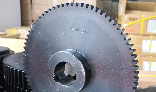
1. What Is a Thin Spur Gear?
A thin spur gear (also called a low-profile spur gear) is a cylindrical gear with a small face width (b) relative to its pitch diameter. In FA (factory automation) equipment, thin spur gears are widely used in compact drive trains where space is limited — printers, scanners, instrument drives, light conveyors, and robotic joints. Because the face width is small, the gear is lightweight and produces lower inertia, but it is also more sensitive to tooth-count selection: too few teeth cause undercutting and weak roots, while too many teeth reduce the available center distance and raise manufacturing cost.
2. Tooth-Count Design Principles
2.1 Avoid Undercut (Minimum Tooth Count)
For a standard 20° full-depth involute spur gear, the minimum number of teeth without undercut is:
z_min ≈ 17 (theoretical limit for 20° pressure angle, no profile shift)
For module m = 1–2 mm, recommend z ≥ 18 to keep a safe root fillet.
For module m < 1 mm (fine-pitch, common in thin gears), recommend z ≥ 20 because the absolute tooth size is small and undercut has a larger relative effect.
Undercut weakens the tooth root and should be avoided in power-transmitting pairs. Where space forces fewer teeth, use a positive profile shift (see §4.1).
Minimum tooth count vs. module (no profile shift):
| Module m (mm) | Recommended z_min | Reason |
|---|---|---|
| 0.3 – 0.5 | 20 | Fine pitch; undercut risk is relatively large |
| 0.6 – 0.8 | 18 | Balance of size and strength |
| 1.0 – 2.0 | 17 – 18 | Standard full-depth, 20° PA |
| > 2.0 | 17 | Larger module tolerates standard min |
2.2 Respect the Minimum Center Distance
The center distance of a spur-gear pair is fixed by module and tooth counts:
a = m · (z₁ + z₂) / 2
Where z₁ is the pinion (small gear) and z₂ is the wheel. Once the layout fixes a, the sum (z₁ + z₂) is determined; you then choose the individual tooth counts around that sum. For a given a, a smaller m allows more total teeth (finer, quieter mesh) but each tooth is weaker; a larger m allows fewer, stronger teeth but coarser meshing and more noise.
2.3 Keep the Contact Ratio Above 1.2
The contact ratio (ε) is the average number of tooth pairs in contact. For smooth, low-noise operation:
ε ≥ 1.2 (absolute minimum for continuous drive)
ε ≥ 1.4 (recommended for thin gears and quiet running)
Raising tooth count and/or face width raises ε. With a very thin face width, ε can fall below 1.2 if the tooth count is too low — so thin gears especially benefit from slightly higher z.
2.4 Use the Standard Module Series and Round Center Distances
Prefer standard module values to ensure cutter and stock availability:
0.3, 0.4, 0.5, 0.6, 0.8, 1.0, 1.25, 1.5, 2.0, 2.5, 3.0 mm (per ISO 54 / GB/T 1357)
For thin and fine-pitch gears, 0.3–1.0 mm modules dominate. The table below lists common combinations that land on round center distances, simplifying the housing layout.
Standard center-distance combination reference (common modules):
| Module m (mm) | z₁ (pinion) | z₂ (wheel) | Center distance a (mm) | Note |
|---|---|---|---|---|
| 0.5 | 20 | 20 | 10.0 | Equal pair, compact |
| 0.5 | 16 | 24 | 10.0 | Unequal, same a |
| 0.8 | 17 | 33 | 20.0 | Avoids undercut (z₁ = 17) |
| 1.0 | 17 | 23 | 20.0 | Reference design |
| 1.0 | 20 | 20 | 20.0 | Equal pair |
| 1.5 | 17 | 23 | 30.0 | Heavier duty |
| 2.0 | 17 | 18 | 35.0 | Coarse, high load |
2.5 Profile Shift (Addendum Modification)
When the minimum center distance is tight, a positive profile shift (x > 0) moves the tooth profile outward, allowing z < 17 without undercut and strengthening the pinion root. Profile shift also lets you fine-tune the center distance and backlash. See §4.1 for a worked example.
3. Practical Recommendations
Unequal-size pairs (pinion & wheel): For a speed-reduction pair, keep the pinion z₁ ≥ 17 (or use profile shift). A small pinion with too few teeth is the usual failure point.
Impact or reversing loads: Raise the tooth count and/or face width by ~10–20% to lower the load per tooth and reduce pitting risk.
Injection-molded (plastic) gears: Avoid very high tooth counts (e.g., z > 60) because the mold becomes expensive and flash/short-shot risk rises; keep z in the 12–48 range and use a larger pressure angle (20° or 25°) for easier demolding.
Face width (b): Thin gears typically use b = (4–10)·m. Increasing b raises load capacity and ε, but also raises misalignment sensitivity — keep shafts parallel and bearings rigid.
4. Calculation Example
4.0 Base case — printer gear pair
A compact printer mechanism requires a center distance a = 20 mm.
Trial 1: m = 1.0, z₁ = 13, z₂ = 27 → a = 1.0·(13+27)/2 = 20.0 mm. ✓ on center distance, but z₁ = 13 < 17 → undercut, weak pinion.
Revised: m = 0.8, z₁ = 17, z₂ = 33 → a = 0.8·(17+33)/2 = 20.0 mm. ✓ Center distance preserved, z₁ = 17 avoids undercut, quieter mesh.
4.1 Profile-shift example — allowing a 13-tooth pinion
Suppose space only allows z₁ = 13 at m = 1.0. The minimum profile-shift coefficient to avoid undercut for a 20° gear is approximately:
x_min ≈ (17 − z) / 17 (for 20° full-depth)
For z = 13: x_min ≈ (17−13)/17 ≈ 0.235. Apply x₁ = +0.25 to the pinion. This shifts the pinion teeth outward, eliminates undercut, and thickens the root. The operating center distance becomes:
a′ = a + m·(x₁ + x₂)
With x₁ = +0.25, x₂ = 0, the new center distance a′ = 20.0 + 1.0·0.25 = 20.25 mm — only 0.25 mm more, usually acceptable. If the housing fixes a = 20.0 mm, set x₂ = −0.25 to keep a′ = 20.0 (balanced shift), trading some wheel-root strength for pinion strength.
5. Failure Mode & Troubleshooting
| Symptom | Likely cause | Remedy |
|---|---|---|
| Broken tooth at root | Undercut (z < 17) or overload | Raise z or add profile shift; increase module/face width |
| Excessive noise | Low contact ratio (ε < 1.2), coarse mesh | Increase z and/or face width; use finer module |
| Rapid wear / pitting | Insufficient face width, misalignment | Widen b; improve shaft/bearing rigidity |
| Backlash too large | Worn or wrong class | Select tighter backlash grade (§9); replace |
| Plastic gear chipping | Too many teeth, poor demolding | Reduce z; use 20°/25° PA; review mold |
| Jamming | Center distance too small | Recompute a; check profile shift sign |
6. Design Checklist
Tooth count z₁ ≥ 17 (or justify with profile shift)
Module m from standard series
Center distance a = m(z₁+z₂)/2 matches layout
Contact ratio ε ≥ 1.2 (target 1.4)
Face width b = (4–10)·m selected
Profile shift x decided if z < 17
Backlash class specified (§9)
Material & process (metal / injection molding) confirmed
7. FAQ
Q: Can I use a 12-tooth thin gear? Only with a positive profile shift and verified root strength; otherwise avoid.
Q: Why does my thin gear whine? Likely ε < 1.2 or too-coarse module — raise z or use finer m.
Q: Plastic vs metal thin gears? Plastic for light, low-noise, cost-sensitive; metal for torque/impact.
Q: How thin is "thin"? Roughly b/d ≤ 0.1–0.15 (face width / pitch diameter); there is no strict standard.
8. Application-Based Selection Matrix
| Application | Module m (mm) | Pinion z₁ | Wheel z₂ | Face width b | Note |
|---|---|---|---|---|---|
| Office printer / scanner | 0.4 – 0.8 | 16 – 20 | 20 – 40 | (5–8)·m | Quiet, fine pitch |
| Instrument / meter drive | 0.3 – 0.5 | 12 – 18* | 20 – 50 | (4–6)·m | Use profile shift if z₁ < 17 |
| Light conveyor roller | 1.0 – 1.5 | 17 – 20 | 20 – 40 | (8–10)·m | Higher load |
| Robotic joint (low torque) | 0.5 – 1.0 | 17 – 24 | 24 – 48 | (6–8)·m | Backlash-controlled |
| Packaging mechanism | 1.0 – 2.0 | 17 – 20 | 20 – 36 | (8–10)·m | Impact loads: raise z |
| Injection-molded device | 0.5 – 1.0 | 12 – 30 | 12 – 48 | (5–7)·m | Keep z ≤ 48 for mold cost |
* Use positive profile shift when z₁ < 17.
9. Backlash & Tolerance Grade Reference
Thin gears in positioning drives need a specified backlash class. Common references:
| Standard | Grade | Typical backlash (m = 1, mm) | Use |
|---|---|---|---|
| JIS B 1702-2 | f (fine) | 0 – 0.03 | Precision positioning |
| JIS B 1702-2 | g (medium) | 0.03 – 0.07 | General automation |
| JIS B 1702-2 | h (coarse) | 0.07 – 0.12 | Low-cost, non-critical |
| DIN 3967 | small / lower | similar bands | EU-equivalent |
For zero-backlash needs (e.g., indexing), use a spring-loaded or split-gear design rather than a tight class alone.
Copyright © 2016-2025 Forrun (Guangdong) Industrial Technology Co., Ltd All Rights Reserved.


