- Contact Us
- -
- Payment
- -
- 中文版
Knowledge Center · 2026-10-15 09:21:00 · 19 hits
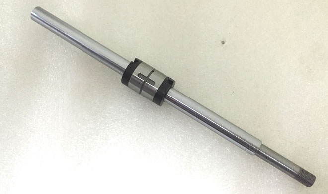
1. Structure and Working Principle
A ball spline is a precision transmission component that combines rotary and linear motion. It consists of a spline shaft, a spline nut (outer race), and recirculating balls. The balls roll within the shaft raceways to transmit torque while allowing the nut to slide smoothly along the axis. This design delivers simultaneous, gap-free torque transmission and linear travel — a high-rigidity compound motion with essentially zero backlash.
2. Advantages in High-Precision Systems
Ball splines outperform conventional slide splines across the metrics that matter in precision automation.
| Advantage | What it means | Why it matters |
|---|---|---|
| High accuracy & repeatability | Rolling contact, extremely low friction → micron-level positioning | Ideal for CNC tables, semiconductor equipment, optical inspection |
| High rigidity & torsional strength | Multi-point ball contact resists bending and twist | Stable under high speed and varying load |
| Low friction, low wear, long life | Recirculating-ball structure replaces sliding friction | Supports high-frequency start-stop control; extends service life |
| Compact, highly integrated | Carries both radial load and torque in one unit | Reduces need for separate guides/bearings; tighter layout |
| Smooth, quiet motion | Rolling contact vs. sliding | Lower vibration/noise — suited to cleanrooms and precision assembly |
3. Typical Application Scenarios
Ball splines are used wherever synchronized rotation and linear motion must be controlled together.
| Application | Role of the ball spline |
|---|---|
| High-precision positioning stages | Linear-rotary compound motion with micron repeatability |
| Robot joints | Torque transmission + axial compliance in a compact envelope |
| Electronic component insertion systems | Fast, accurate plunge-and-rotate placement |
| Auto-focus mechanisms | Smooth axial travel synchronized with rotation |
| Linear-rotary servo modules | Integrated shaft that both drives and guides |
| Semiconductor / optical equipment | Clean, low-vibration motion in controlled environments |
Their performance is especially pronounced in systems requiring simultaneous rotary and linear control.
4. Selection and Usage Guidelines
Select the raceway type and size according to required torque and thrust (axial force).
Prefer a high-hardness shaft material such as SUJ2 (JIS bearing steel, ≈ AISI 52100 / DIN 100Cr6) or SUS440C (stainless bearing steel) to maximize rigidity and wear life.
Maintain coaxiality and assembly accuracy to prevent eccentric loading.
Lubricate regularly and protect against dust and chips to keep the balls rolling freely.
Selection parameter quick-map:
| Requirement | Reasons for Recommendation |
|---|---|
| High torque transfer | Larger shaft diameter / more raceways |
| Long stroke + rotation | Standard ball spline with full recirculation |
| Corrosive / washdown | SUS440C stainless shaft + suitable lubricant |
| Cleanroom use | Low-particle lubricant; sealed nut option |
5. Summary
With their high precision, high rigidity, and low friction, ball splines have become a core component of modern high-precision positioning systems. Through sound selection and precise installation, they significantly improve equipment response speed and positioning stability.
6. Ball Spline vs. Conventional Slide Spline
The advantages cited above become concrete when compared directly with the traditional sliding (dry/sliding-contact) spline.
| Criterion | Ball spline | Conventional slide spline |
|---|---|---|
| Friction mechanism | Rolling (recirculating balls) | Sliding |
| Efficiency | High (~90%+) | Lower |
| Backlash | Near zero | Inherent clearance |
| Wear rate | Low | Higher |
| Positioning precision | Micron-level | Coarser |
| Noise / vibration | Low | Higher |
| Torque rigidity | High (multi-point contact) | Moderate |
| Load capacity | High, with rigidity | Moderate |
| Lubrication sensitivity | Moderate | Higher |
| Cost | Higher | Lower |
Bottom line: choose a ball spline when precision, rigidity, and life justify the cost; a slide spline remains viable for low-duty, cost-sensitive, or infrequent-motion uses.
7. Rated Torque and Service Life
Ball splines are rated by a basic dynamic torque rating C (catalog value, in N·m), which depends on shaft diameter and the number of raceways. Service life under a constant applied torque T follows the standard ball-element life relation:
L = (C / T)³ × 10⁶ revolutions
where:
C = rated torque (N·m)
T = equivalent applied torque (N·m)
L = rated life in revolutions (90% survival, Lundberg–Palmgren basis)
To convert revolutions to operating hours at rotation speed n (rpm):
L_h = L / (60 · n)
Worked example: A spline with C = 50 N·m runs at an applied torque T = 25 N·m and rotation speed n = 300 rpm.
L = (50 / 25)³ × 10⁶ = 2³ × 10⁶ = 8 × 10⁶ revolutions
L_h = 8 × 10⁶ / (60 × 300) ≈ 444 hours
Note: this is a simplified torque-only estimate. In real positioning systems the shaft also carries axial (thrust) and radial loads and undergoes combined rotary-linear cycles. Always apply the manufacturer's combined-load / combined-motion life method, and derate for shock, contamination, and inadequate lubrication.
Copyright © 2016-2025 Forrun (Guangdong) Industrial Technology Co., Ltd All Rights Reserved.


