- Contact Us
- -
- Payment
- -
- 中文版
Knowledge Center · 2026-11-14 09:10:46 · 19 hits
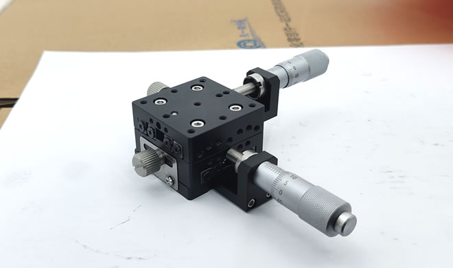
This guide examines the adjustment requirements along the X, Y, and Z directions and analyzes the travel, load capacity, accuracy, guide structure, and mounting methods of manual translation stages. It compares single-axis combinations with integrated three-axis platforms, explains how different applications demand specific adjustment ranges and load ratings, and provides a reference for selecting stages used in laboratories, inspection equipment, and automated tooling.
1. What Are the Functions of X, Y, and Z Translation Stages?
A manual X/Y/Z translation stage is typically built from three linear adjustment mechanisms oriented along three orthogonal directions. Movement is controlled by handwheels, micrometer heads, or adjustment screws, enabling precise positioning of workpieces, sensors, lenses, or inspection components.
The three axes serve distinct purposes:
X-axis stage: Provides horizontal left-right movement, suited to lateral positioning and scanning.
Y-axis stage: Provides forward-backward movement within the horizontal plane, working with the X-axis to achieve two-dimensional planar positioning.
Z-axis stage: Provides vertical lift adjustment, commonly used for focus adjustment, height compensation, and up-down positioning.
Combined as three axes, the assembly delivers spatial positioning in all three directions and is widely used in optical inspection, microscope imaging, experimental testing, precision assembly, and automated equipment.
Note that X, Y, and Z merely label the direction of motion. In actual installation, the orientation of each axis should be determined according to the equipment's coordinate system; not every three-axis stage adopts an identical structural layout.
2. What Parameters Matter When Selecting a Three-Axis Manual Stage?
2.1 Determine Travel from the Adjustment Requirement
Travel is the first parameter to define during selection. X and Y axes are typically used for in-plane positioning, while the Z axis handles height and focus adjustments.
For small-range precision fine adjustment, choose a short-travel fine-positioning stage; if a larger positioning range is also required, select a long-travel stage.
Bear in mind that greater travel is not always better. Increasing travel usually changes platform size, moving mass, and structural rigidity, which can affect positioning stability.
2.2 Determine Load Capacity from Workpiece Weight
When three axes are combined, load cannot be judged from a single axis's rated capacity alone.
For example, when a Z-axis stage is mounted on X/Y-axis stages, the X and Y axes must support not only the workpiece weight but also the upper-stage assembly, connecting plates, and other mounting accessories.
Therefore, calculate the actual load on each axis separately, and pay particular attention to the Z axis's vertical load capacity and the overturning moment caused by the center-of-gravity offset.
2.3 Determine Accuracy from Positioning Requirements
The positioning capability of a manual stage is generally related to its guide mechanism, transmission structure, micrometer head resolution, and mechanical backlash.
For general positioning, focus on smooth motion and repeatability. For microscopes, optical inspection, or precision measurement, focus on minimum incremental movement, repeatability, straightness, and pitch/yaw error.
Distinguish between the scale resolution of the micrometer head and the actual positioning accuracy of the stage—the two are not identical.
2.4 Select the Guide Structure Based on Usage Frequency
Common guide structures include cross-roller guides, ball guides, and other precision sliding guides.
Cross-roller guides offer good motion smoothness and rigidity, suited to precision fine adjustment. Ball guides suit applications with larger travel and higher load demands. Sliding guides require judgment based on friction characteristics and adjustment accuracy.
Selection should reference the product's load capacity, motion resistance, accuracy grade, and service-life parameters.
2.5 Select the Drive Structure Based on Operation Method
Common manual adjustment methods include micrometer-head adjustment, handwheel adjustment, and screw adjustment.
Micrometer-head adjustment: Suited to small-travel, high-precision fine adjustment.
Handwheel adjustment: Convenient to operate, suited to larger-range positioning.
Screw adjustment: Relatively simple structure, suitable for general positioning.
If the equipment requires frequent fine adjustment, also consider whether the scale direction, operating clearance, and locking mechanism are convenient to use.
3. How Should the X, Y, and Z Axes Be Combined?
Three-axis manual stages are generally configured in two ways.
3.1 Combining Three Single-Axis Stages
Stack X, Y, and Z stages sequentially using connecting plates to form a three-dimensional adjustment structure.
The advantage is flexible configuration—you can select different specifications for each direction's travel, load, and accuracy, and it simplifies later replacement or maintenance.
However, pay attention to stacking order, overall height, connection rigidity, and center-of-gravity position. Especially when the Z axis is mounted on top, verify the bottom stage's load capacity and overturning moment.
3.2 Choosing an Integrated XYZ Three-Axis Platform
An integrated three-axis platform combines the three directional motions into a single assembly, usually with a compact structure and well-defined mounting interfaces.
This suits equipment with limited installation space or a desire to reduce connecting components, but each axis's travel, load, and structure may be constrained by the product series, offering relatively lower selection flexibility.
If the accuracy requirements differ significantly across the three directions, an independent single-axis combination usually allows more targeted configuration.
4. How Should Different Application Scenarios Be Selected?
| Application Scenario | Selection Priorities |
|---|---|
| Microscopy & optical inspection | Micrometer head resolution, repeatability, motion smoothness |
| Laser & optical component adjustment | Fine adjustment, locking stability, angular adjustment needs |
| Laboratory sample positioning | Adjustment travel, operational convenience, platform load capacity |
| Automated equipment tooling adjustment | Load, structural rigidity, mounting interface |
| Sensor & camera position adjustment | XYZ travel, installation space, repeat adjustment capability |
If optical path calibration is involved, also determine whether an additional angular adjustment mechanism is required. A standard XYZ linear stage adjusts position only along three directions and cannot directly replace pitch, yaw, and rotation adjustment platforms.
5. What Problems Are Easily Overlooked During Procurement and Installation?
Ignoring total height after stacking: Combining three axes increases overall height, which may affect equipment layout and operating range.
Looking only at single-axis rated load: Upper stages and accessories also load the lower stage; verify load and moment based on the actual combined state.
Ignoring the locking mechanism: After precision adjustment, an unreliable lock may allow position drift under external vibration or handling.
Focusing only on scale resolution: A fine micrometer scale does not guarantee equivalent actual positioning accuracy—consider guide error, backlash, and structural deformation.
Neglecting mounting interfaces: Before purchasing, confirm hole patterns, thread specifications, connecting-plate dimensions, and base interfaces to avoid on-arrival installation problems.
In summary, selecting an X/Y/Z manual translation stage should start from the actual adjustment task: first define the travel and load for the three directions, then match accuracy, guide structure, and operation method. For precision applications, also consider the rigidity, stability, and error transmission of the stacked assembly—do not judge overall performance from a single axis's parameters alone.
FAQ
Can a single-axis translation stage be used alone?
Yes. A single-axis stage independently performs one-direction positioning; an XYZ three-axis structure is needed only when spatial three-dimensional positioning is required.
What are the requirements for XYZ three-axis installation order?
The order is determined by equipment structure and adjustment needs. A common approach is to install the X and Y horizontal adjustment mechanisms first, then the Z lift mechanism. However, the specific sequence should be designed around the product's mounting interfaces, load distribution, and center-of-gravity position.
Is a higher micrometer head resolution always better?
Not necessarily. Higher resolution theoretically allows finer scale adjustment, but actual positioning depends on guide accuracy, transmission backlash, stage rigidity, and operational stability.
Why pay special attention to load capacity for a Z-axis manual stage?
The Z axis typically bears vertical gravity. Excessive load may cause platform sag, difficult adjustment, or post-lock position shift; therefore, check the rated load, holding capability, and anti-drop design.
Copyright © 2016-2025 Forrun (Guangdong) Industrial Technology Co., Ltd All Rights Reserved.


